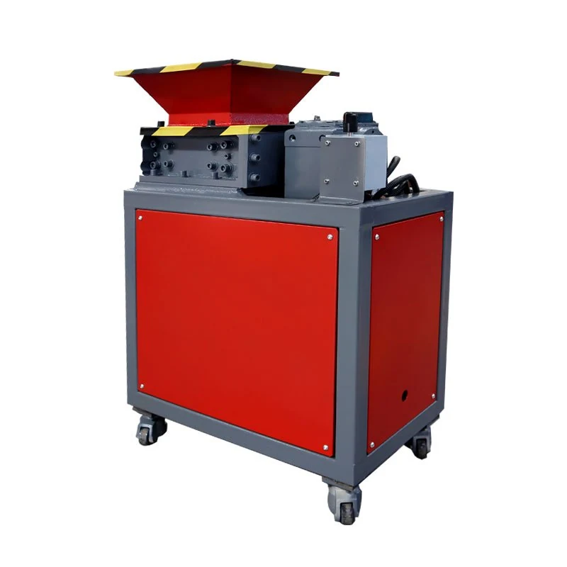
Review the complete molding waste stream
Injection molding sprues, runner frames, trims and rejected parts can be evaluated for size reduction close to production. The right configuration depends on the actual pieces, their material and the result required by the next process.
FYXFER SHRED starts with manageable routine scrap when reviewing a compact machine. Larger, thicker, reinforced or irregular pieces may require a different cutting arrangement or a heavy-duty platform. Include both everyday scrap and the most demanding pieces in the initial enquiry.
Measure the whole frame and its thickest sections
A runner branch diameter does not describe the space needed for the complete frame. Measure its maximum length, width and height, then record the largest runner diameter and central-sprue thickness separately. For rejected molded parts, include the thickest wall, rib, boss or solid section.
A broad, lightweight frame can bridge across a hopper or catch on its branches. A thick central sprue can impose a different cutting load from the surrounding runners. Provide an overall photograph with a scale and close-up photographs of these demanding areas.
When should pre-cutting be considered?
Review pre-cutting when the uncut frame exceeds the approved opening, bridges during feeding, contains sections outside the confirmed cutting range or cannot be loaded safely and consistently. Another hopper or machine configuration may be appropriate. Send the uncut frame details so both approaches can be compared.
Nominal hopper dimensions do not establish the safe usable opening. Guarding, feeding clearance, operator access and the cutting chamber must be checked together.
Identify the resin and formulation
PP, HDPE, ABS and PC are examples for evaluation. Their names alone do not confirm suitability. Grade, wall thickness, flexibility, temperature and geometry can change feeding and cutting behavior.
Disclose glass fiber, other fillers, flame retardants, metal inserts and mixed materials where known. Also identify moisture, dirt, labels, residues and tooling fragments. These details affect machine selection, wear and the preparation needed before processing. Ask for a site-specific noise and dust review when planning operation beside molding personnel.
Choose the machine from feed and output requirements
| Waste or process condition | Route to review |
|---|---|
| Routine, manageable runners and smaller rejects | FY-SS01-300 compact configuration, subject to material and feeding confirmation. |
| A different compact size or integrated secondary reduction | FY-SS01 series, selected around the actual feed and downstream objective. |
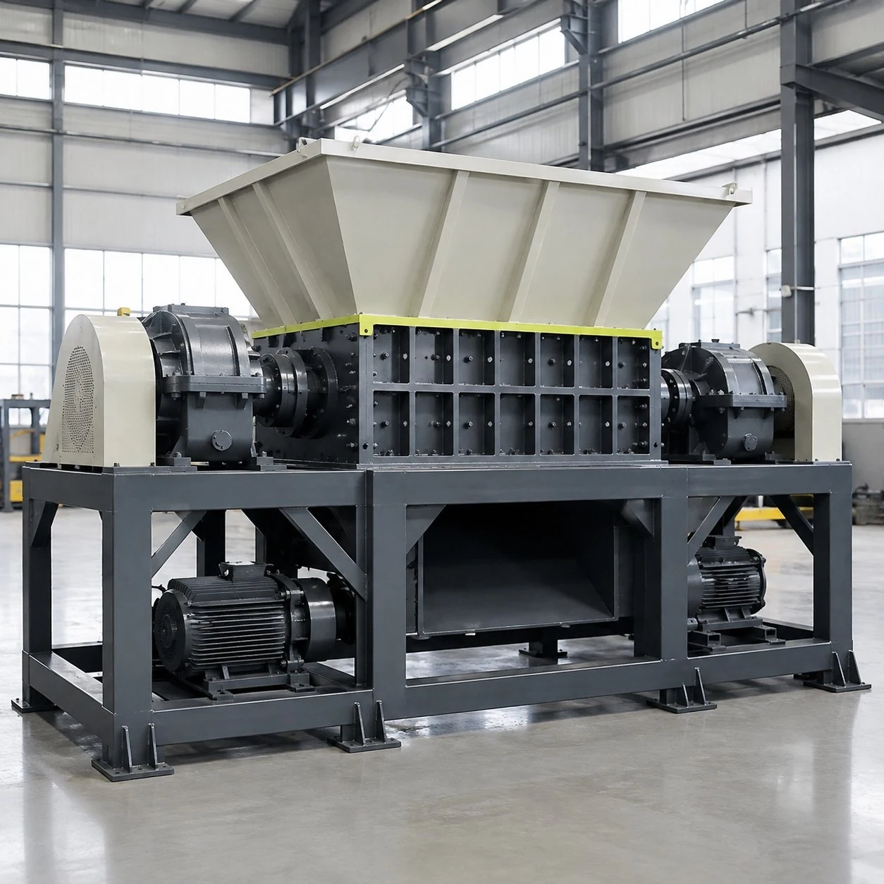
| Bulky, thick, tough, mixed or highly irregular feed | FY-SS02 project platform, with application-specific cutters, drive and handling. |
Explain whether the output will be collected, conveyed, sorted, granulated or reused. Primary shredding and fine granulation serve different objectives; a second processing stage may be needed for a defined regrind result. A screen or another discharge arrangement must suit the selected machine and material.
Prepare a representative sample and define acceptance
When a trial is requested, agree the sample contents with the review team. Include normal pieces and the largest, thickest or toughest pieces expected in production. Describe normal moisture and contamination and disclose inserts or reinforced grades. Do not add undisclosed materials to the batch.
Record how feed arrives: continuous flow, individual parts or batches after mold changes and quality checks. Provide weighed kg per hour or shift where possible, plus peak batch size and operating hours. A daily average can hide a demanding short feeding period.
Set the required output range, downstream use and acceptance method before the trial. Suitability, throughput and output must be confirmed for the tested material, feeding conditions and selected configuration. Motor power alone does not establish the result.
Build a photo brief for the whole molding job
| View or measurement | Include | Why it is useful |
|---|---|---|
| Complete runner frame | Length, width, height, branch layout and a scale in the photograph. | Shows the space needed for feeding and possible bridging. |
| Central sprue and junctions | Largest diameter or thickness and close-ups of dense connections. | Identifies sections that can impose a different cutting load. |
| Rejected molded parts | Overall dimensions, thick walls, ribs, bosses and inserts. | Prevents a thin runner sample from representing a much tougher reject. |
| Typical collection batch | Resin or formulation labels, weight, collection method and batch frequency. | Connects material review with the real loading pattern. |
Keep different formulations identified. A resin name such as PP or ABS does not describe glass fiber, fillers, flame retardants, inserts or the condition in which the waste reaches the shredder.
Set up a comparison that answers the real question
Should the sample contain whole frames or prepared pieces?
Agree both the intended feed condition and any preparation being evaluated. If pre-cutting is considered, record that step so a successful test on prepared pieces is not mistaken for proof that the whole frame can enter and process directly.
Can the output go straight back into molding?
State the downstream material and particle requirements before making that assumption. Primary shredding and granulation have different roles; further reduction, sorting or other preparation may be needed for the intended reuse.
Which production conditions belong in the test brief?
Include normal and difficult pieces, material grade, moisture or temperature where relevant, contamination and the expected batch pattern. Record the sample weight, feeding conditions and output observations against the agreed acceptance method.
Does a successful result apply to another resin or mold?
A changed formulation, thicker junction, larger frame or different insert can change feeding and cutting. Describe those changes before applying a previous result to a new waste stream.
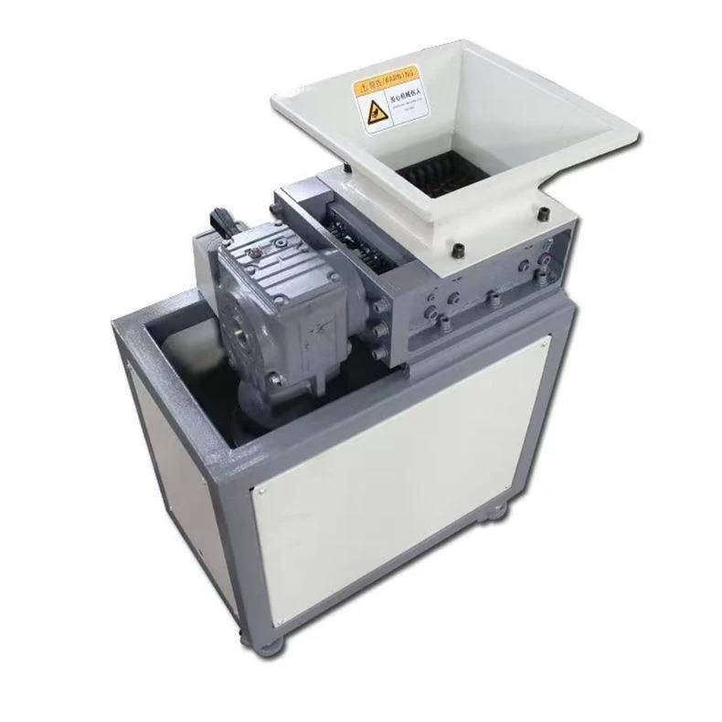
The equipment photographs here are configuration references. They are not sample-test results or proof of a particular resin, model, output size or production rate.
Send a complete application enquiry
Combine resin and grade, whole-frame dimensions, maximum runner diameter, central-sprue thickness, rejected-part thickness, photographs, contamination, workload and required output. Add manual, bin-tip or conveyor feeding, available floor space, loading height, collection method, and destination voltage, frequency and phase.
Review the technical documents and discuss your sprues and runners with FYXFER SHRED. The quotation, drawings and agreed acceptance criteria define the final machine scope.