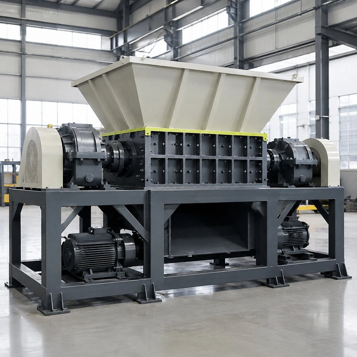
Plan demanding primary reduction and the line layout
FY-SS02-1200 is a published large project class for demanding primary reduction and engineered line layouts. It is part of the FY-SS02 heavy-duty dual-shaft platform for suitable bulky, tough or variable industrial material.
Drive, cutters and dimensions are confirmed by the approved drawing. A 1200 project should therefore start with the material and process requirements, supported by the installation limits and the intended feeding and discharge arrangements.
FY-SS02-1200 configuration reference
| Item | Basis for review |
|---|---|
| Model | FY-SS02-1200 |
| Project class | Large class for demanding primary reduction and engineered line layouts |
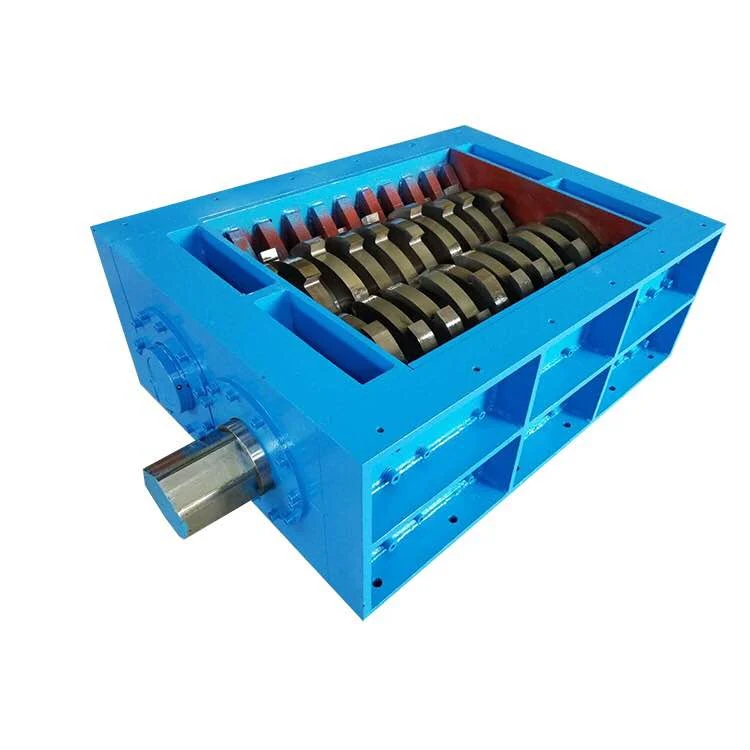
| Cutting system | Dual shaft; cutter geometry selected for the material and required result |
| Drive | Project-defined; drive, cutters and dimensions require approved drawings |
| Feed opening, dimensions and weight | Confirm in the approved project drawing |
| Throughput and output size | Confirm against actual feed, loading, configuration and duty |
Bring demanding feed and installation limits into one review
For the 1200 class, prepare the difficult-material evidence and the engineered line layout together. A proposed reduction process needs a practical place for loading, discharge and service before the machine arrangement is fixed.
- Material envelope
- Record the largest and most resistant pieces, their composition and contamination, including the loading condition in which they arrive.
- Site envelope
- Show floor space, height limits, doors, columns, surrounding machinery and the route used to bring equipment into position.
- Process result
- Define output, operating pattern and downstream use so the machine and its location are assessed against the same task.
Follow the primary-reduction route through the layout
The platform uses dual-shaft engagement, tearing and shearing for suitable demanding feed. Review where material enters and exits that process alongside the drawing for the hopper, drive, frame and supporting equipment.
- Show how the largest approved pieces reach the hopper through the proposed loading system.
- Assess the cutter and drive proposal against normal and difficult feed under defined conditions.
- Review collection or onward transfer, including the space below and around the discharge.
- Check that the installation leaves the access needed for inspection and planned maintenance.
Bring the material review and layout review together
Supply details of the most difficult expected feed along with the space available for the machine and supporting equipment. Review loading, discharge and maintenance access as part of one layout. Final machine dimensions and weight should come from the confirmed project documents.
- Material construction, normal and maximum dimensions, resistant sections and contamination.
- Required output, expected hourly or daily volume and operating duty.
- Site layout, loading method, discharge route and access around the equipment.
- Power supply, downstream process and the planned interfaces with other equipment.
Agree what the proposed configuration must demonstrate
Use representative material to review the cutting arrangement and define acceptance criteria. Specify the required output distribution, how oversize pieces will be assessed and the operating conditions used for the review. The agreed result should relate to the supplied material and configuration, rather than a general class label.
Does 1200 specify the chamber or overall machine width?
Neither dimension is established by the model code alone. The usable feed opening, cutting chamber and overall equipment envelope require confirmation in the approved drawing. Do not plan installation clearance from the name.
Resolve drawing questions before fixing neighbouring equipment
Use the approved project drawing to coordinate interfaces and access. The class name does not provide foundation dimensions, lifting information or a maintenance envelope.
- Confirm machine dimensions, weight, positioning and lifting information before the installation plan is finalised.
- Identify component-removal routes and access for cutter inspection and cleaning under the agreed isolation procedure.
- List site-supplied platforms, conveyors or collection equipment and their control connections so the line arrangement remains coordinated.
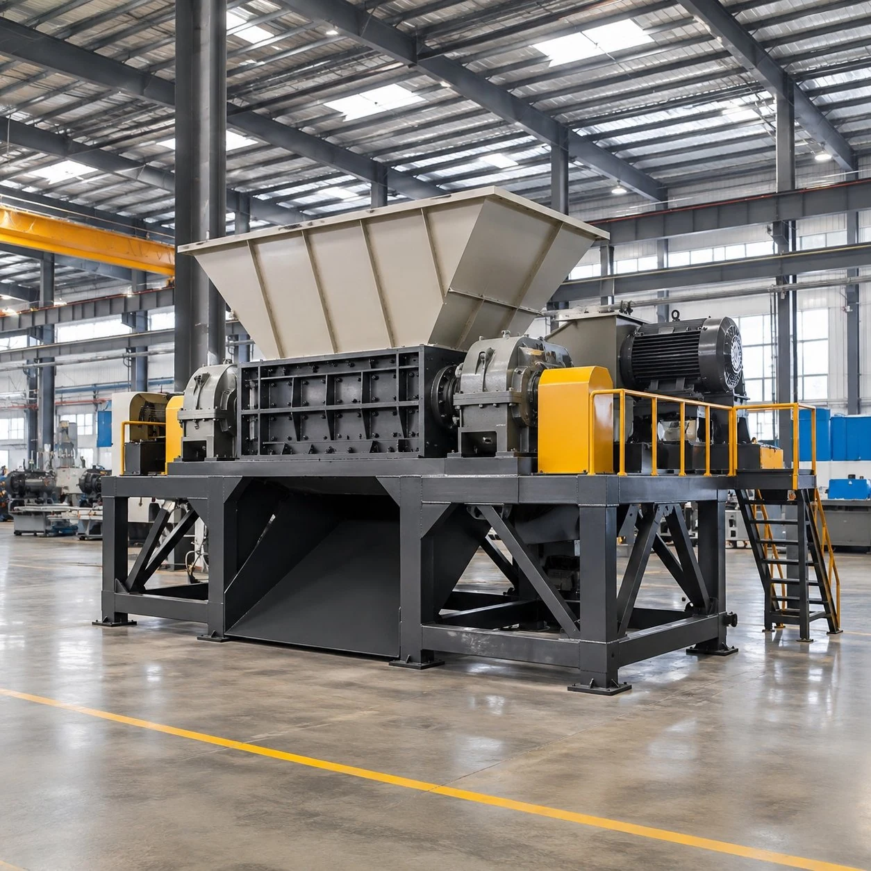
FY-SS02-1200 Heavy-Duty Dual-Shaft Shredder — practical questions
Can civil or installation planning begin from the model name?
Use the name to identify the project discussion, then obtain the approved dimensions, weight and interface information. The code is not a substitute for an installation drawing.
What evidence should support the cutting proposal?
Provide representative normal and difficult feed, with material condition and loading stated. Agree the required output and operating criteria and, where testing is used, record how those criteria are measured.
How does the 1400 comparison differ?
The published 1400 positioning emphasises bulky-feed systems and supporting equipment. Compare the full piece-handling and line requirements using the same material evidence rather than assuming a numerical size step.
Prepare your FY-SS02-1200 review
Send material photographs, the most difficult expected pieces and the process information above. Final specifications, options and acceptance criteria should be recorded in the project quotation and approved drawings.
Download the FY-SS02 series selection guide (PDF) for the shared selection framework. It is a series reference, not a final specification for this model.
Review FY-SS02-1400 · Return to the FY-SS02 series · Discuss your material with FYXFER SHRED