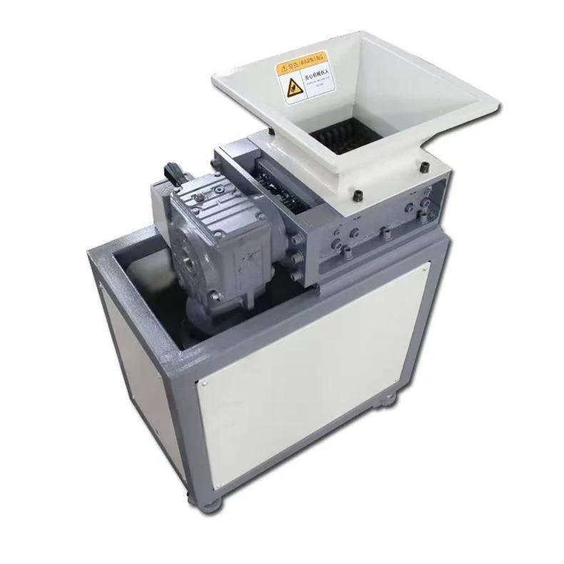
An integrated upper and lower cutting route
The FY-SS01-300-2S combines two cutting stages in a four-shaft arrangement. The published reference lists a 3 kW upper drive and a separate 3 kW lower drive. Upper cutters are 24 discs at Ø180 × 12 mm; lower cutters are 28 discs at Ø180 × 10 mm. The stages are listed at 15 and 21 rpm respectively.
Review this configuration when one integrated machine needs an initial reduction step followed by a secondary cutting stage. The two stages are part of the process arrangement; neither cutter thickness nor the 2S name establishes a guaranteed final particle size.
FY-SS01-300-2S reference specification
These published values describe a reference configuration. Final supply follows the approved quotation and drawings.
| Parameter | Reference value |
|---|---|
| Layout | Integrated two-stage, four-shaft |
| Upper drive | 3 kW |
| Lower drive | 3 kW |
| Reference supply | 380 V, three phase |
| Upper cutter speed | 15 rpm |
| Lower cutter speed | 21 rpm |
| Upper cutters | 24 discs; Ø180 × 12 mm |
| Lower cutters | 28 discs; Ø180 × 10 mm |
| Feed dimensions | Confirm against the project drawing |
| Reference weight | Approximately 1,200 kg |
Cutter dimensions are diameter × thickness; the listed quantity is the disc count. Throughput and output size must be established for the actual material and feeding conditions.
Start with a reason for using two cutting stages
A two-stage assessment begins with the condition of the incoming scrap and the condition required after the lower stage. State whether the process needs easier collection, preparation for another machine or a defined output range. This allows both stages to be considered as one material route.
- Incoming geometry
- Show complete runner frames or rejected parts, their thickest sections and any preparation before loading.
- Material composition
- Identify polymer, fillers, reinforcement and contamination, keeping materially different streams labelled during review.
- Final acceptance
- Describe the downstream use and how the discharged sample will be assessed, including long pieces or fines when relevant.
Review the upper-to-lower material route
The upper and lower cutter sets have separate roles in the integrated arrangement. The review should follow material through both stages and then into collection, rather than assessing only the first reduction step.
- Confirm the usable hopper opening and how the original scrap reaches the upper stage.
- Review initial reduction at the upper stage using the proposed feed condition and difficult pieces.
- Assess the complete two-stage result against the lower-stage configuration and the downstream acceptance method.
- Check how the final output leaves the machine so collection or transfer does not restrict the overall process.
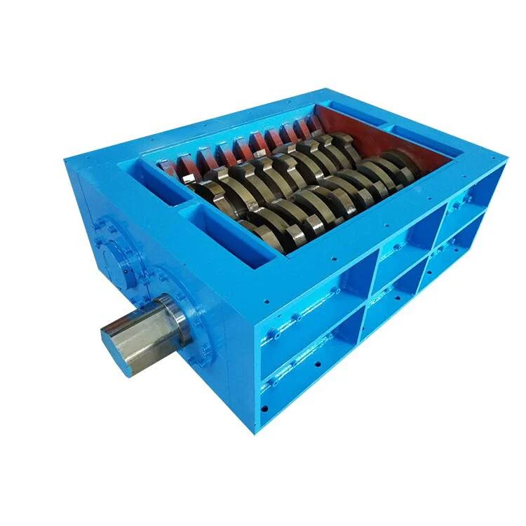
Keep the 300 and 300-2S configurations distinct
The FY-SS01-300 is the standard compact reference with a single listed 3 kW drive and a 16 rpm cutter-speed reference. The 300-2S lists separate upper and lower drives and speeds, so the 300 values must not be copied into both stages. Compare the FY-SS01-400-2S if the material review requires a different two-stage configuration.
Related configurations: FY-SS01-300 · FY-SS01-400-2S · FY-SS01-500-2S.
Specify the result after both cutting stages
Provide representative feed and state the output condition needed by the next process. Include how acceptable output will be checked, the required amount per shift, contamination and any difficult sections. Review the feed opening and complete installation drawing; the usable feed dimensions must be confirmed for this model.
Send the required processing amount as a project target, along with the operating pattern and acceptance method. It is not a proven capacity derived from motor power. For branched moulding waste, use the sprue and runner checklist.
Allow access to both cutting stages
Ask for a complete arrangement drawing showing the feed route, stage positions, discharge and service access. The installation review should cover the integrated machine, its collection equipment and how components will be reached for approved maintenance.
- Identify the inspection, cleaning and cutter-service access for both stages and the required component-removal space.
- Keep the upper and lower cutter sets identified separately in parts and maintenance records.
- Confirm the control, guarding and isolation procedure for the complete machine and agree which handling equipment is included.
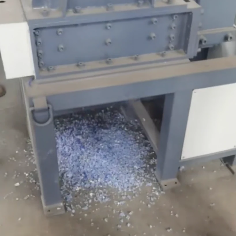
FY-SS01-300-2S Two-Stage Shredder — practical questions
Can a standard 300 trial predict a 300-2S result?
A standard-machine trial can help describe the incoming material, but it does not demonstrate the integrated upper and lower arrangement. Review a result representative of the proposed process and its actual cutter sets.
Does the lower cutter thickness define finished particle size?
It describes a cutter dimension. The discharged size distribution also depends on the feed and complete cutting and discharge arrangement. Define the required result and inspect a representative sample.
What should be compared with the 400-2S?
Use the same material, loading pattern and output criteria. Compare the proposed cutter sets, feeding arrangement and complete process result; model class alone does not provide a reliable performance ratio.
Compare the range and prepare your enquiry
Download the FY-SS01 series selection guide (PDF) for the wider reference range, or return to the FY-SS01 series comparison.
For bulky or mixed waste outside a compact production-scrap workflow, review the FY-SS02 platform. Include FY-SS01-300-2S and your material details when you contact FYXFER SHRED.