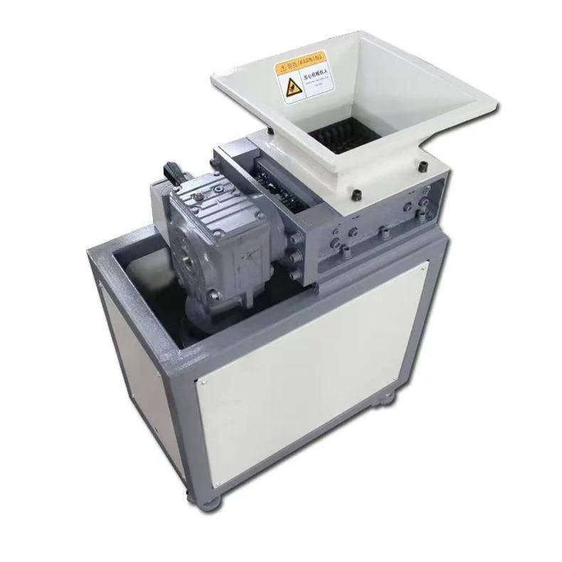
Compare two separate cutter sets in a 4 / 4 kW reference
The FY-SS01-400-2S is an integrated two-stage, four-shaft configuration. Both the upper and lower drives are listed at 4 kW. The upper stage uses 26 cutters at Ø180 × 15 mm; the lower stage uses 49 cutters at Ø180 × 8 mm. Its published upper speed is 15 rpm, while the lower speed requires confirmation.
The separate cutter sets provide a defined starting point for reviewing feed and secondary reduction needs. The lower cutter count and thickness do not by themselves establish a final output size. Confirm the complete arrangement against representative material and the required downstream result.
FY-SS01-400-2S reference specification
These published values describe a reference configuration. Final supply follows the approved quotation and drawings.
| Parameter | Reference value |
|---|---|
| Layout | Integrated two-stage, four-shaft |
| Upper drive | 4 kW |
| Lower drive | 4 kW |
| Reference supply | 380 V, three phase |
| Upper cutter speed | 15 rpm |
| Lower cutter speed | To be confirmed |
| Upper cutters | 26 discs; Ø180 × 15 mm |
| Lower cutters | 49 discs; Ø180 × 8 mm |
| Feed dimensions | Confirm against the project drawing |
| Reference weight | Confirm in the quotation |
Cutter dimensions are diameter × thickness; the listed quantity is the disc count. Throughput and output size must be established for the actual material and feeding conditions.
Match the two cutter sets to the required result
The 400-2S has distinct upper and lower cutter references, so the selection discussion should address both the incoming pieces and the material expected after the second stage. Use actual scrap to explain why another cutting step is needed.
- Feed challenge
- Identify the largest part, thickest section and material grade, then show how it will be prepared and loaded.
- Output challenge
- Explain the next process and identify unacceptable long pieces, fines or other characteristics that need assessment.
- Operating pattern
- Record weighed batches and the available processing time so the review covers the intended work rather than an isolated easy sample.
Evaluate both stages before fixing the installation
Follow the material through the upper reduction step, the lower cutting arrangement and final discharge. Resolve the unlisted lower-stage speed and feed dimensions in the project documents while this process review is taking place.
- Agree the prepared condition and orientation of the incoming scrap at the hopper.
- Review how the upper cutting set handles normal material and the thickest or most resistant pieces.
- Assess the resulting output after the lower stage using the required downstream size and handling criteria.
- Include collection and removal of the finished batch when evaluating the complete operating route.
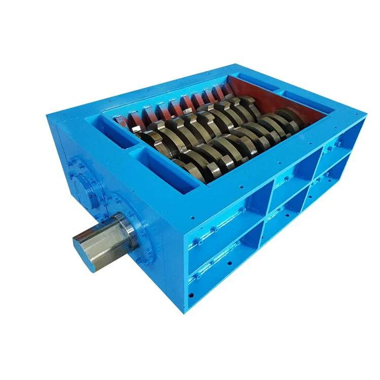
Compare the stage arrangement, not only the model number
The FY-SS01-300-2S reference lists 3 / 3 kW drives and different upper and lower cutter sets. The 400-2S should be selected through feed and output review, not by scaling the 300-2S processing rate. The standard FY-SS01-400 has a single listed 4 kW drive and a 12 rpm reference; its speed and layout do not describe this two-stage machine.
Related configurations: FY-SS01-300-2S · FY-SS01-400 · FY-SS01-500-2S.
Resolve the unlisted values before final selection
Confirm the lower-stage speed, feed dimensions and machine weight in the quotation and drawing. Supply maximum part dimensions, thickest sections, material grade and contamination, then define the acceptable output and how it will be assessed. Include the loading method, collection arrangement and destination power supply.
Send the required processing amount as a project target, along with the operating pattern and acceptance method. It is not a proven capacity derived from motor power. For branched moulding waste, use the sprue and runner checklist.
Keep stage-specific maintenance information together
The different cutter sets should remain identifiable in the operating and service information. Request the complete arrangement and parts documentation before committing the surrounding equipment or maintenance space.
- Confirm access for inspection, cleaning and cutter service at each stage, with safe isolation defined for the full machine.
- Provide the collection route and space for removing material so discharge does not compete with the service area.
- Discuss reinforcement, inserts and abrasive contamination when agreeing wear criteria and spare-parts needs.
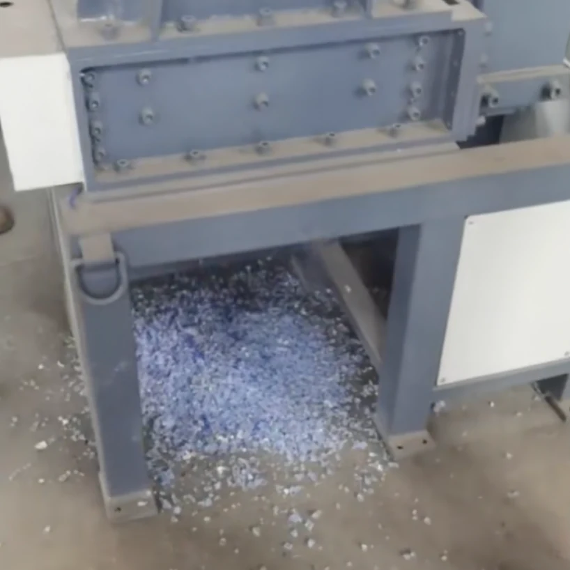
FY-SS01-400-2S Two-Stage Shredder — practical questions
Why is the lower cutter count relevant?
It identifies the published lower-stage hardware and keeps it distinct from the upper set. The count is useful for configuration and parts review, but does not establish the final output distribution by itself.
Which details need confirmation before placing the machine?
Confirm the feed and installation drawing, machine weight, lower-stage speed, service access and discharge arrangement. These values should be supplied for the ordered configuration before the site layout is fixed.
How should I compare the 300-2S and 500-2S?
Use one description of the actual feed and required final result for both alternatives. Review their proposed stage arrangements, handling and acceptance evidence without copying missing specifications between models.
Compare the range and prepare your enquiry
Download the FY-SS01 series selection guide (PDF) for the wider reference range, or return to the FY-SS01 series comparison.
For bulky or mixed waste outside a compact production-scrap workflow, review the FY-SS02 platform. Include FY-SS01-400-2S and your material details when you contact FYXFER SHRED.