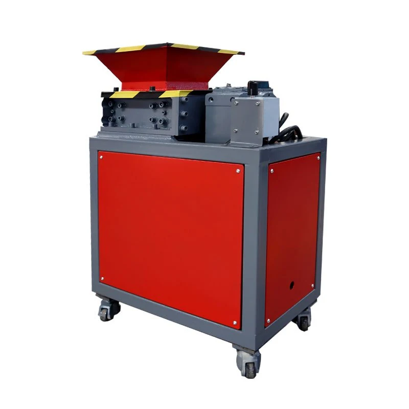
Choose a compact shredder around your production scrap
The FY-SS01 series covers seven published configurations: four compact standard models and three integrated two-stage, four-shaft models. Start with the size, shape and behaviour of your material, then compare the cutting arrangement and required downstream result.
FYXFER SHRED brings these configurations together for factory scrap selection. A larger model number or a higher motor rating alone does not establish throughput, output size or suitability for a particular material.
Find a starting configuration · Compare compact references · Compare two-stage references
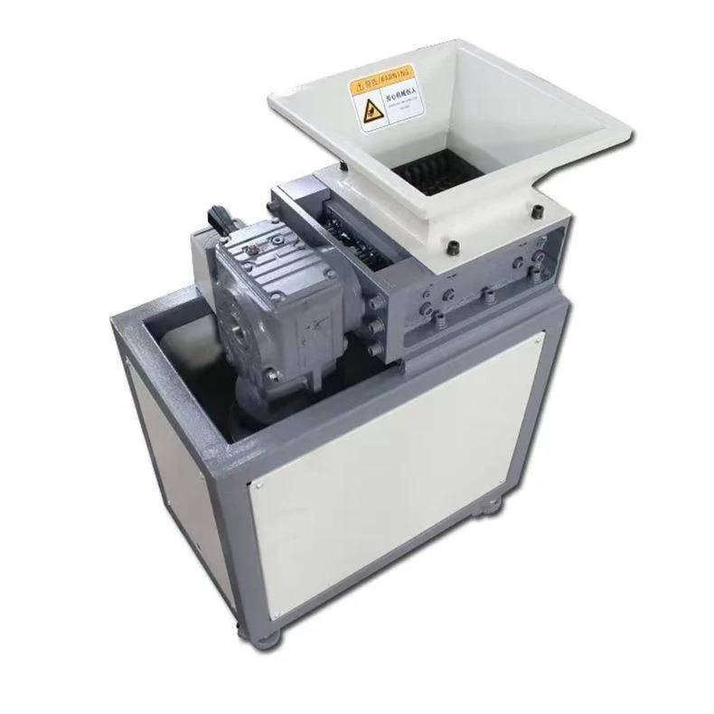
Start with the feed and reduction task
- Small pieces and light intermittent work: review FY-SS01-180 when a compact machine is important and the material fits the confirmed chamber and feeding arrangement.
- Routine plastic production scrap: start with FY-SS01-300 for suitable runners, trims, offcuts and manageable rejected parts.
- Larger or tougher routine feed: compare FY-SS01-400 and FY-SS01-500 after reviewing maximum piece size, thickness and material behaviour.
- An integrated secondary reduction step: review the 300-2S, 400-2S and 500-2S upper/lower cutting arrangements when the required output calls for a finer reduction path.
- Bulky, mixed or demanding waste: compare the FY-SS02 heavy-duty platform before selecting a compact machine.
For injection moulding waste, the sprue and runner selection page explains why complete frame dimensions and the thickest branch both matter.
Standard compact models: published reference configurations
These values describe the source reference builds. Cutter notation below gives disc count × diameter × thickness. Feed references are not a statement of the largest piece that can safely enter the machine.
| Model | Drive and supply | Cutter speed | Cutters | Feed or chamber reference | Reference weight |
|---|---|---|---|---|---|
| FY-SS01-180 | 1.5 kW; 220 V, 1 phase | 25 rpm | 21 × Ø90 × 8 mm | 180 × 190 mm chamber | Approx. 120 kg |
| FY-SS01-300 | 3 kW; 380 V, 3 phase | 16 rpm | 24 × Ø180 × 12 mm | 500 × 500 × 300 mm feed reference | Approx. 400 kg |
| FY-SS01-400 | 4 kW; 380 V, 3 phase | 12 rpm | 26 × Ø180 × 15 mm | 600 × 500 × 300 mm feed reference | Approx. 500 kg |
| FY-SS01-500 | 7.5 kW; 380 V, 3 phase | 15 rpm | 24 × Ø200 × 20 mm | 700 × 700 × 350 mm feed reference | Approx. 750 kg |
The 180 entry describes a chamber; the other entries are published feed references. They should not be treated as equivalent usable openings. Check the approved drawing, feeding clearance and actual scrap dimensions when comparing models.
Two-stage, four-shaft models
The 2S configurations combine an upper and a lower cutting stage in one machine. The upper and lower drives and cutters are listed separately because both stages affect the reduction path.
| Model | Upper / lower drive | Upper cutters | Lower cutters | Upper / lower speed |
|---|---|---|---|---|
| FY-SS01-300-2S | 3 / 3 kW | 24 × Ø180 × 12 mm | 28 × Ø180 × 10 mm | 15 / 21 rpm |
| FY-SS01-400-2S | 4 / 4 kW | 26 × Ø180 × 15 mm | 49 × Ø180 × 8 mm | 15 rpm / confirm lower speed |
| FY-SS01-500-2S | 11 / 7.5 kW | 24 × Ø200 × 20 mm | 32 × Ø200 × 15 mm | 15 rpm / confirm lower speed |
The published supply for these three models is 380 V, three phase. The 300-2S reference weight is approximately 1,200 kg. The 500-2S lists a 700 × 700 × 350 mm side hopper. Other feed dimensions, the lower speeds marked above and unlisted weights require the project drawing or quotation.
A second stage does not establish a guaranteed particle size. Specify the acceptable output and test representative material to assess the complete configuration.
Connect the model comparison to the output you need
The compact equipment views on this page are configuration references. They do not identify a verified photograph of every listed model or show the internal layout of each two-stage build.
| Decision | Compact route | Integrated 2S route |
|---|---|---|
| Reduction objective | Define the condition needed for collection, transfer or the next process. | Explain what further reduction is required after the upper cutting stage. |
| Feed description | Whole-part dimensions, thickness, grade, contamination and loading. | The same feed review, plus the required result after both stages. |
| Reference comparison | Read drive, cutter speed and geometry together with the feed reference. | Keep upper and lower drives, cutters and speeds separate. |
| Confirmation | Check usable feed clearance and representative material. | Check both stages as one configuration and agree output acceptance. |
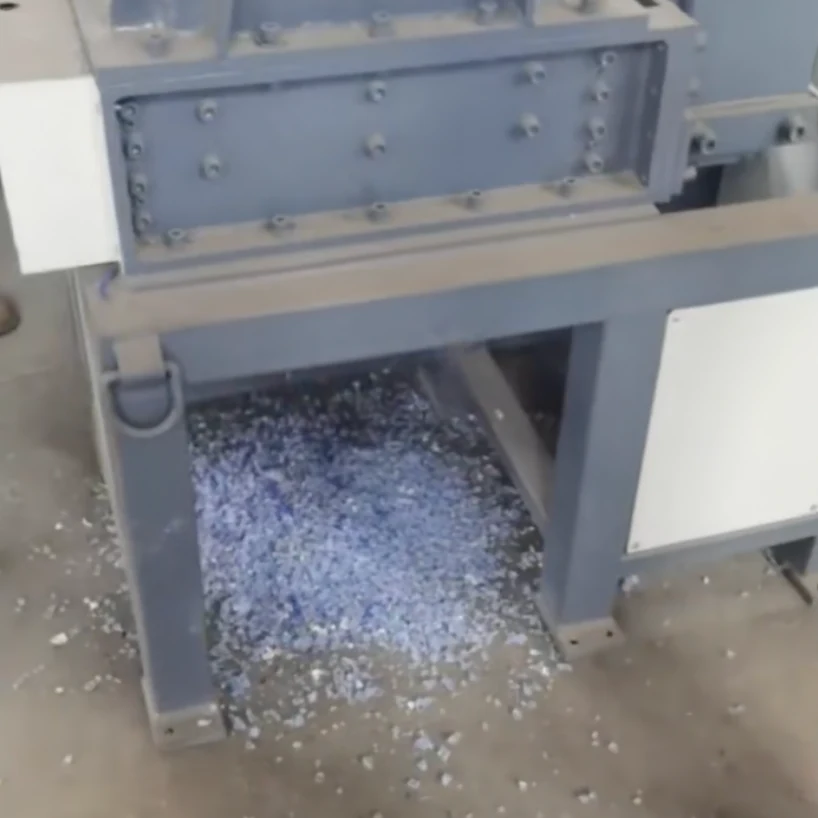
Why can the same motor rating give different practical results?
Material geometry, density, flexibility, feeding consistency and the required output all affect the cutting task. A regular stream of manageable parts differs from intermittent large pieces or a changing mixture. Include the normal loading pattern when comparing configurations.
Does the reference feed dimension describe every part that can enter?
No. Review the whole part, its orientation and the usable opening with the guarding and cutting arrangement. A chamber reference and a hopper reference are different measurements; the approved drawing and material review determine the suitable loading arrangement.
Prepare a production-scrap comparison
- Separate grades or material streams that may need different cutting arrangements.
- Show normal pieces and the largest, thickest or most awkward pieces expected in production.
- Identify the required output and the next process before requesting a finer reduction path.
- Agree sample conditions, loading and the method for checking output and processed amount.
Use the individual model links in the reference tables for the published details. Missing lower-stage speeds, feed dimensions or weights stay subject to confirmation; they should not be copied from a neighboring model.
Define the job before choosing the final model
Send photographs and the material grade, normal and maximum dimensions, wall thickness, moisture and contamination. Include the amount to process per hour or shift, feeding method, required output condition, downstream process, available space and destination power supply.
Keep the required processing amount separate from a proven machine capacity. Throughput, output size, duty and application suitability depend on the actual material and confirmed configuration. Final supply follows the approved quotation and drawings.
Read the FY-SS01 selection guide or prepare your project enquiry. You can also return to the shredder comparison.